
Franke Triflow Doric Handle & Valve Changing Guide
Franke Triflow Doric Spec sheet with part numbers.

Franke Triflow Doric Spec sheet with part numbers
Connectors:
9.030617 – G ¼ m X ¼ Push fit connector – used to connect the green tube to the plastic housing
9.030618 – G ¼ m x 3/8 Push fit connector – used to connect the blue tube to the plastic housing
Tubing:
9.280403 green tube – ¼ x 1m green hose that connects to the plastic Triflow housing
9.280408 blue tube – 3/8 x 1m blue hose that connects the plastic hoses to the stop valve ( FR9502)
Valve and Vernier Insert Changing Procedure for the Franke Doric Mixer Tap.
(For ease of use this guide shows only 2 handles but the procedure is the same for all 3 handles of
your tap)
It should be an easy matter to change the Valve and Vernier Insert if you follow these simple
instructions and refer to the diagram below.
1) Turn off the water supplies to the mixer tap. Place plug in to waste to prevent loss of small pieces.
2) Remove Boss A. by unscrewing in an anticlockwise direction from Valve C, once free pull off
FOR VERNIER INSERT CHANGING PROCEDURE:
3) The Vernier Insert B may be left inside the Boss A or remain on the Valve C. Remove and replace
if damaged.
4) Please go to stage 7 if replacing the Vernier Insert B only.
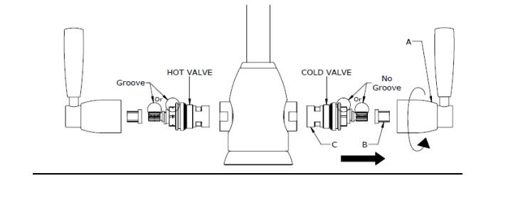
FOR VALVE CHANGING PROCEDURE:
Note: When changing valves note that two valves can be used. One valve has a grove around which
represents the HOT valve, whilst the COLD valve is plain (See diagram). Before removing the valve
the mixer, check that the valve supplied is a suitable replacement.
5) Unscrew Valve C using a 17mm or adjustable spanner.
6) Fit new Valve C to body and tighten firmly. Recommended torque setting 15Nm.
7) Slide Vernier Insert B onto Valve C.
8) Slide Boss A onto Vernier Insert B, just enough to see if it is correctly orientated.
9) To get the exact alignment with the other handle on the tap it may be necessary to remove the
Vernier Insert B and turn a few splines until correct alignment can be achieved.
10) Boss A can now be screwed back over Valve C.
11) The Handle B can now be pushed back over Vernier Insert C.
12) Your tap should now be ready for use, turn on supply and check carefully for any leaks
Franke Triflow Doric Handle Layout